Home >
tubular motors >
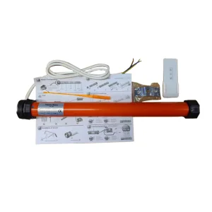
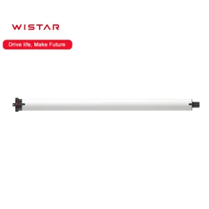
24V DC Brushless Gear Motor Driver Built/in PWM Driven Motor 8W BLDC Planetary Gear Motor Cw/Ccw Reversible Tubular Metal Gear Motor
1 / 5
24V DC Brushless Gear Motor Driver Built/in PWM Driven Motor 8W BLDC Planetary Gear Motor Cw/Ccw Reversible Tubular Metal Gear Motor
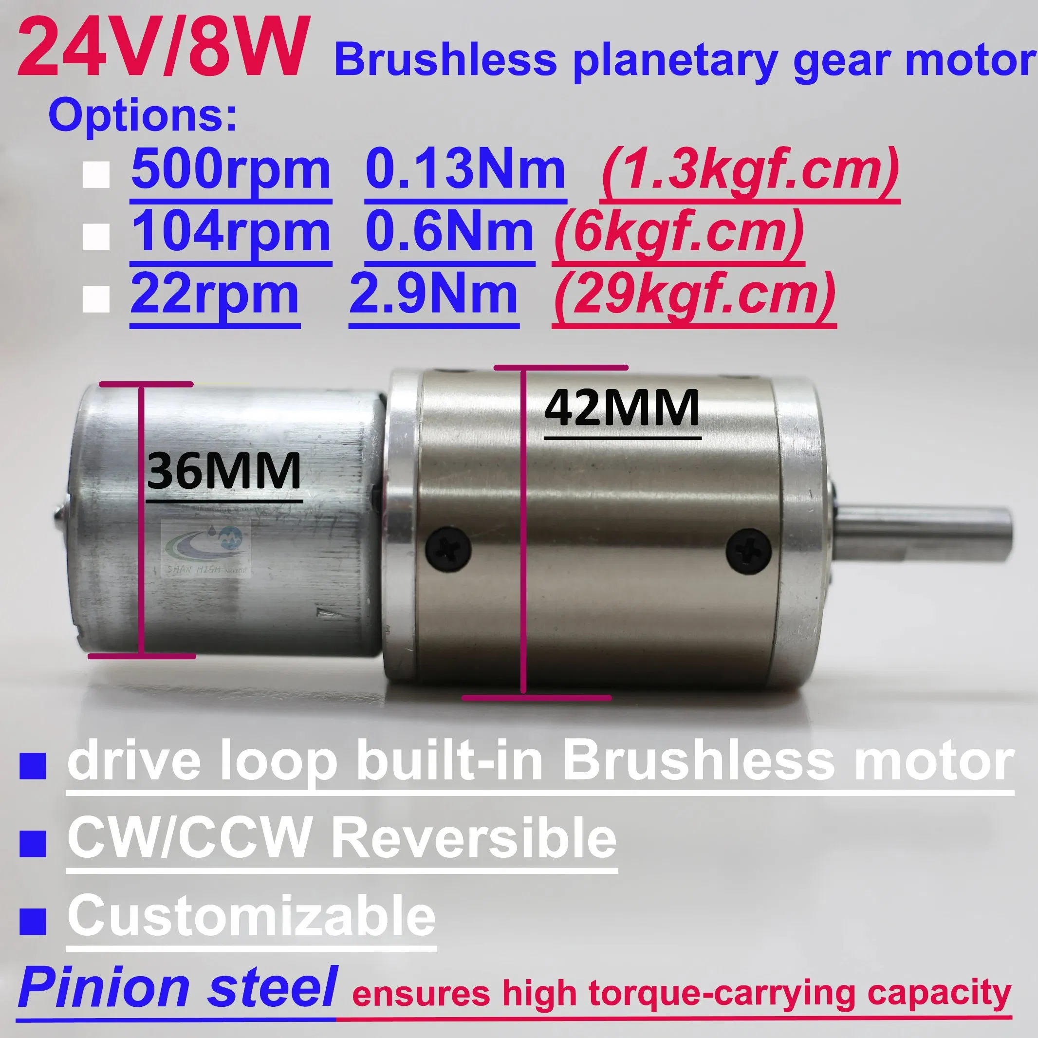
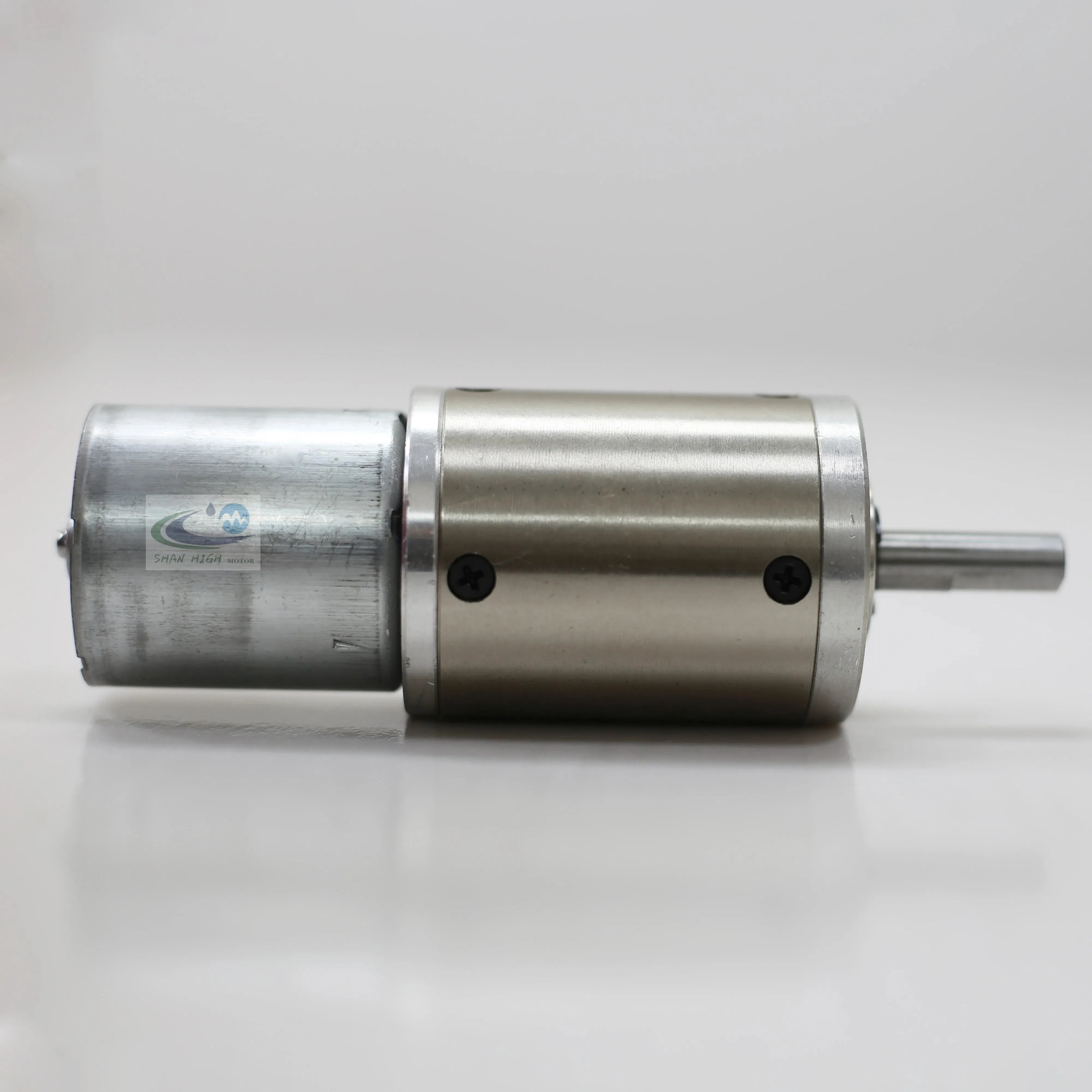
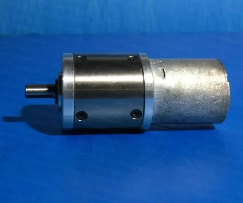
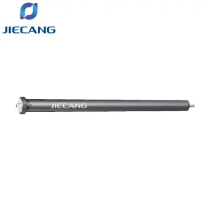
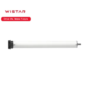
GP42-B2430 BLDC Planetary Gear Motor
The gear reducer is a planetary gear reducer fabricated from high-grade metal materials. Following quenching and heat treatment, the gears achieve optimal performance status, ensuring the gearbox operates smoothly and with minimal noise output. Benefiting from the characteristics of the self-driving DC brushless motor, required installation space is significantly decreased and the overall mechanical structure is simplified.
2. Technical Parameters of the Gear Motor
Stage of Gearbox
STAGE 1
STAGE 3
STAGE 4
Type No.
GSP-5-42B30
GSP-24-42B30
GSP-116-42B30
Allowable Continuous Speed
500rpm
104rpm
22rpm
Admissible Continuous Torque
0.13 N.m
0.60 N.m
2.90 N.m
Weight
328g
396g
465g
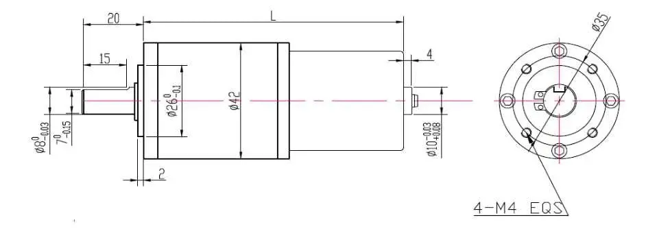
Length "L"
75.0mm
86.0mm
96.0mm
Supply Voltage
DC 24V
Rated Input Current
0.5A
Rated Power of Motor
8W
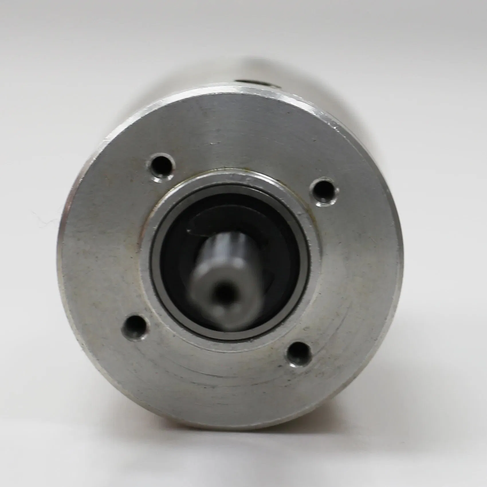
Allowable Radial Load
≤50N
Allowable Axial Load
≤30N
Shaft Press Fit Force, Max.
150N
Operating Ambient Temperature
0ºC ~ 50ºC
Life (H)
10,000 Hours
3. Parameters of Direct Drive DC Brushless Motor
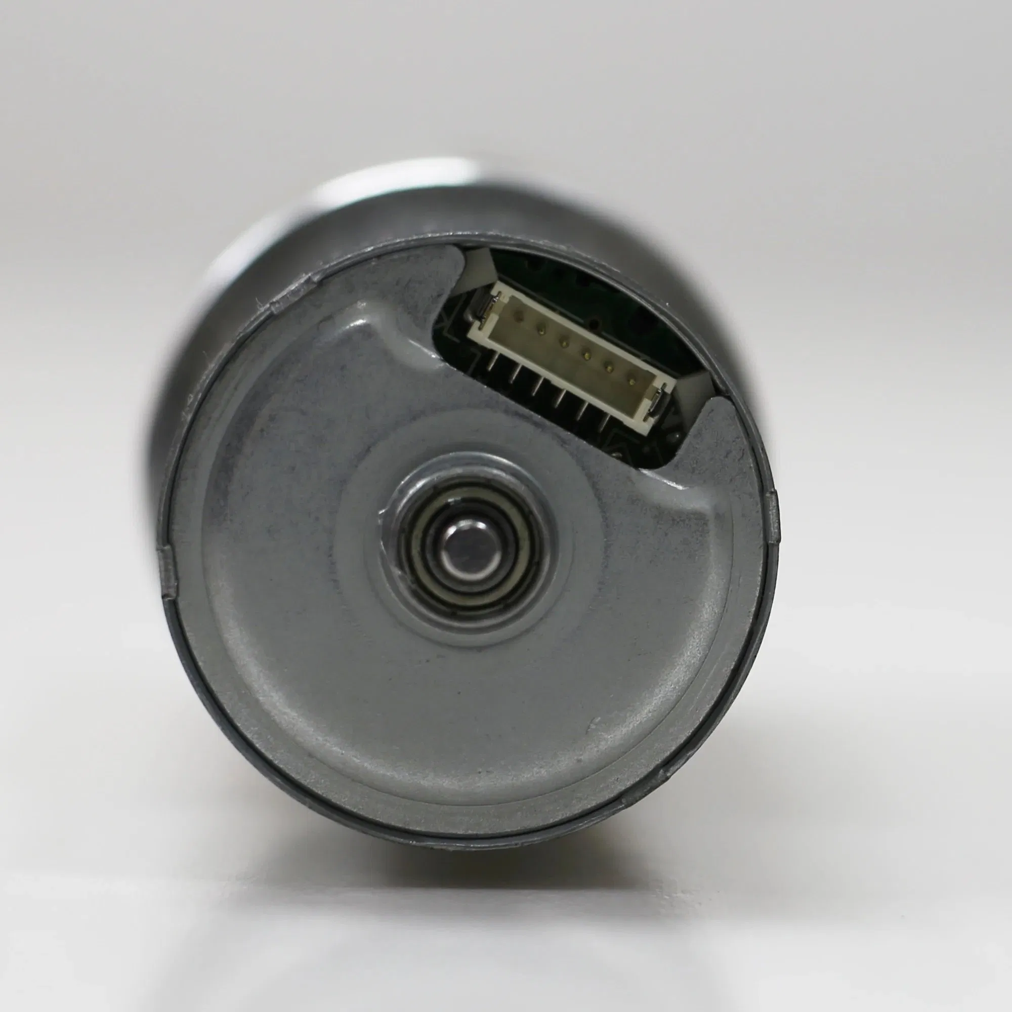
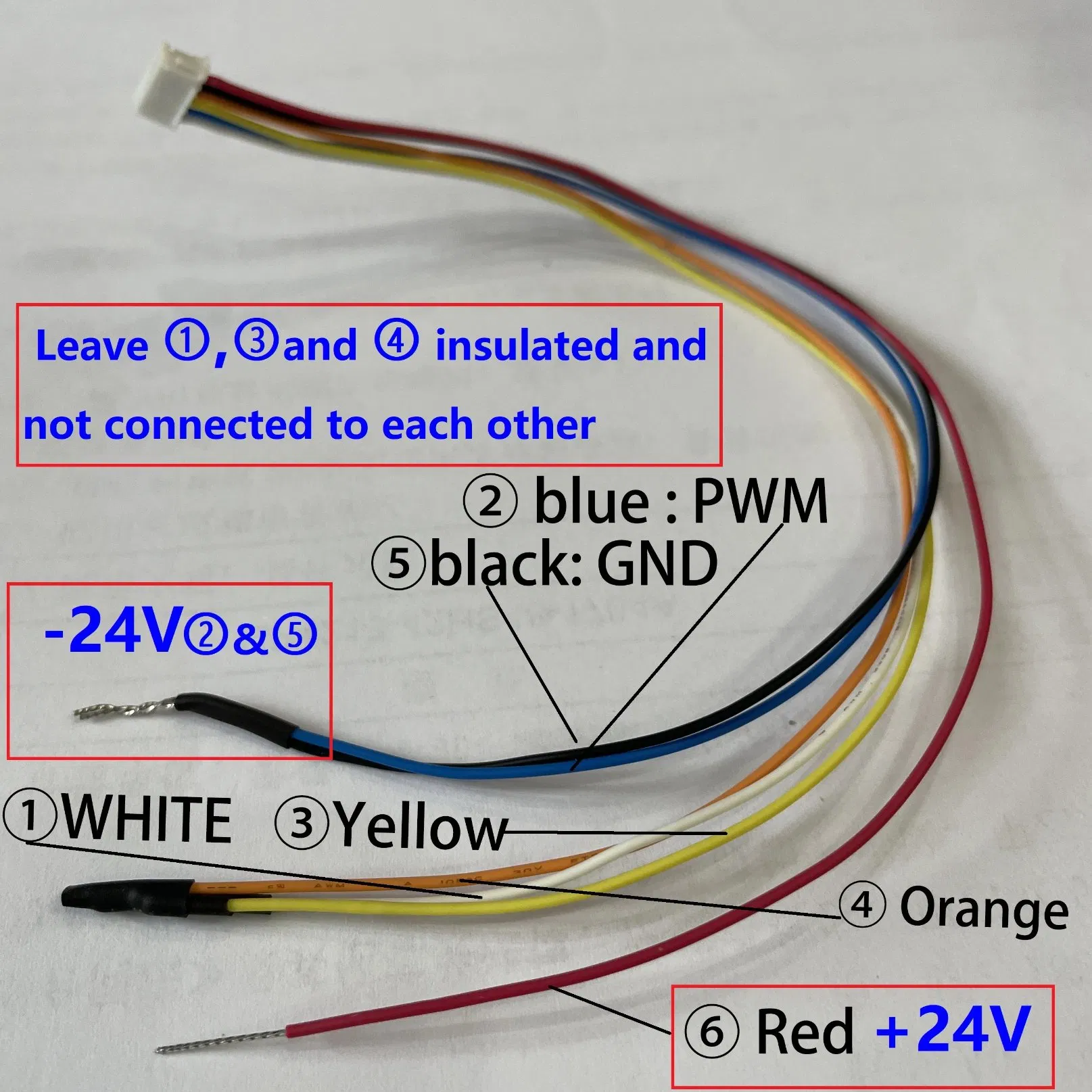
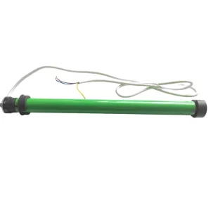
3.1 Pin Wiring Definition of the Brushless Motor
No.
Signal
I/O
Specification
Note
1. WHITE
BRAKE
Input voltage range
IN
0-5V
-
VIH
2.0V Min
High: motor motion
VIL
0.8 Max
Light: motor stop
2. BLUE
PWM
Input voltage range
IN
0-5V
-
VIH
2.0V Min
High: motor motion
VIL
0.8 Max
Light: motor stop
Min. input frequency of PWM
330Hz
The input frequency of PWM is recommended as 20KHz-30KHz
3. YELLOW
1FG
VOH
OUT
6V Max
Because the FG signal output forms as an open drain, it needs to be pulled up on the outside
VOL
0.5V Max
Max. rated current of FG signal synchronization
2mA
Signal pulse number of FG
6 pulses per round
4. ORANGE
CW/CCW
Input voltage range
IN
0-5V
-
VIH
2.0V Min
High: CW
VIL
0.8 Max
Light: CCW
5. BLACK
GND
-
IN
Ground
Ground
6. RED
VM
-
IN
DC24V
Power supply
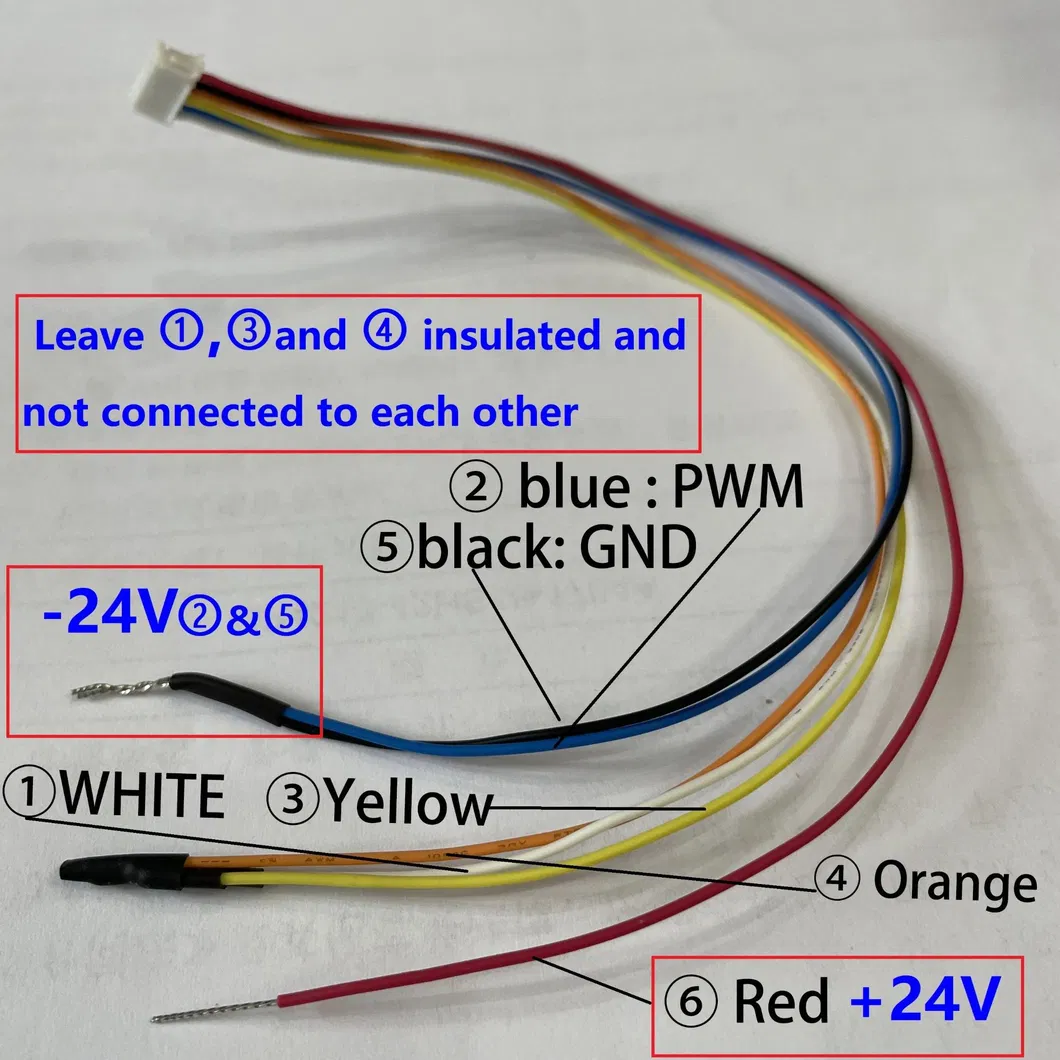
Simple Wiring Method
Connect the wiring as details below to run the motor instantly upon power-on:
Connect Pin 2 (BLUE) & Pin 5 (BLACK) together to the negative (-24V) power supply.
Leave Pin 1, Pin 3, and Pin 4 insulated and disconnected.
Connect Pin 6 (RED) to the positive (+24V) power supply.
*Refer to the connection schematic shown on the left.
3.2 Ratings of the Encoder Motor
No.
Item
Specification
Note
1
Rated Voltage
DC24±10% [V]
_
2
Minimum Operating Voltage
DC16 [V]
_
Max. Operating Voltage
DC26.4 [V]
_
3
Type
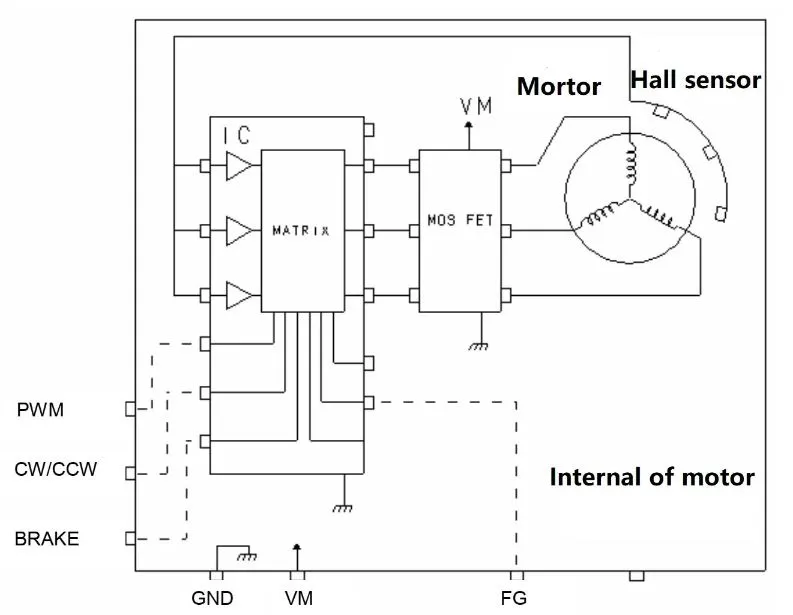
3 phases 12 poles brushless motor with 3 hall sensors
_
4
Rotation Direction
CW/CCW
_
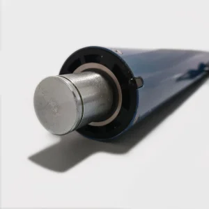
5
Bearing Type
Ball bearing
_
3.3 Electrical Characteristics of the Encoder Motor
No.
Item
Specification
Note
1
Dielectric Strength
AC 600[V] 1[sec] 1[mA] Max
Check between all shorted terminals and motor cover.
2
Insulation Resistance
DC500[V] 10[MΩ] Min
Check between all shorted terminals and motor cover.
3
No Load Current
0.24[A] Max
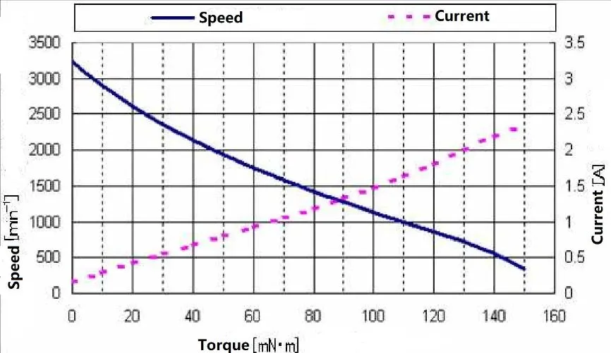
DC24[V], the T-N & T-I characteristic curve for reference as shown in section 3.6.
4
No Load Speed
3300±15% [min-1]
DC24[V], the T-N & T-I characteristic curve for reference as shown in section 3.6.
3.4 Loop Protection Function
No.
Item
Specification
Note
1
Current Limit
3[A] Typ
_
2
Stop Temperature
165[ºC]±15[ºC] IC temperature
When the temperature of the driving IC reaches the specified threshold, the motor automatically stops.
The maximum operating temperature rating of the IC is 150[ºC].
This thermal cutoff function protects the IC from permanent damage by automatically cutting off current when abnormal circuit temperatures occur.
To maintain optimal motor life, avoid triggering this thermal protection under standard operation.
3
Motor Self-Lock Protection
2[sec] Typ
When the motor is locked, it stops automatically within the specified time. Disconnect and reconnect the power supply to restore normal operation.
What are the primary structural advantages of the GP42-B2430 motor?
The motor utilizes a precision-machined planetary gear reducer constructed from hardened metal. Thanks to the self-contained DC brushless driver integration, installation envelope requirements are heavily minimized while the overall mechanical complexity of your system is reduced.
What is the recommended operating voltage and range?
The nominal operating voltage is DC 24V. The system supports a safe operating input voltage range spanning from a minimum of DC 16V to a maximum of DC 26.4V.
What built-in safety protection features are integrated?
The driver circuit features multiple safeguards: 1) A typical 3A current limiting feature; 2) Intelligent motor self-lock protection that powers off the system within 2 seconds if a rotor stall is detected; and 3) An integrated thermal cutoff designed to stop the motor when driver IC temperatures reach 165°C ± 15°C.
What is the operational life expectancy under normal conditions?
Configured with premium industrial ball bearings and precision heat-treated gears, this brushless motor is rated for an exceptional operational lifespan of up to 10,000 hours.
How does the simple wiring override operate for quick testing?
For quick operations without advanced PWM configurations, simply bridge the Blue (PWM) and Black (GND) lines together to your negative power terminal (-24V), isolate the remaining signal cables, and feed +24V straight to the Red (VM) input.
What frequency range is suggested for speed control via PWM?
While the driver board supports a minimum PWM entry frequency of 330Hz, the optimal recommended operational input frequency ranges between 20KHz and 30KHz for clean, linear speed adjustments.